Table Of Content

In addition to these components, the traffic light PCB layout also includes resistors, capacitors, diodes, and transistors, which are used to regulate the voltage and current flow in the system. The PCB layout is designed to ensure that all the components are placed in the correct position and connected with each other properly. In addition to the electronic components, the PCB layout also includes connectors and mounting holes that allow the board to be connected to other components in the traffic light system. These connectors and mounting holes must be carefully placed to ensure that the board can be easily integrated into the system. The PCB layout is an essential component of the traffic light system, as it controls the timing and sequencing of the lights.
Multiplexer (MUX) and Demultiplexer (DEMUX) Applications
Altium Designer is the only application that includes everything in a single program, no external programs are needed to complete a design and prepare it for production. PCB design basics are important because multiple extensive revisions can seriously delay the completion of your project, costing you time and money. It’s important to work with engineering experts from the beginning so that you can design for manufacturability and ensure a final, cost-effective product that works efficiently. Create your manufacturing deliverables within your PCB design process methodology. Schematic organization helps you create the right PCB design process methodology. Manage your components, get real-time supply chain data, access millions of ready-to-use parts.
Ceramics Used in Electronic Applications
CAD tools can be resource-intensive, so it's important to have a computer with sufficient processing power and memory. Check the software's official documentation or website for the specific system requirements. Ensure that your computer meets or exceeds these requirements to avoid any performance issues during the design process.
Figure out those trace widths
By following the above PCB design steps, the process of creating a comprehensive PCB board design is as easy as counting to ten. Using a systematic approach such as this ensures that all aspects of your circuit board design are accounted for inherently during the process, with minimal need to retrace your steps. Altium Designer provides a great deal of flexibility and allows you to quickly place components on your circuit board. You can have your components automatically arranged or you can place them manually. You can also use these options together, which allows you to take advantage of the speed of auto-placement and ensure your board is laid out according to good component placement guidelines. An added advanced feature of this latest version of Altium Designer is the ability to arrange components as groups.
Solder masks, usually made from a polymer coating, are applied to the PCB surface to protect copper traces from oxidation and prevent short circuits during soldering. The solder mask also provides electrical insulation between adjacent traces and pads. Finding reliable printed circuit board manufacturers is integral if you want high-quality PCBs. At Bay Area Circuits (BAC), we specialize in providing top-quality PCB assembly services. We manufacture your PCBs to the highest standards; our years of experience and industry-leading technology guarantee that. The Gerber files contain all the necessary information to fabricate the board, including the copper traces, solder mask, and component placements.
PCB design is like designing a city
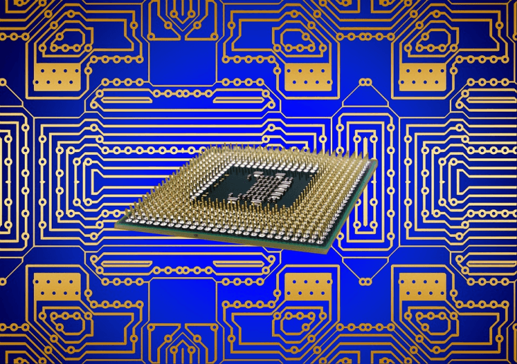
SMD components are now the standard component type used in most applications that require a small form factor, low power, and low cost. However, some applications still make use of through-hole components as they are more reliable and easier to assemble, including with hand assembly. The image below shows an example of a modern PCB with high-density SMD components. PCB designers used to be forced into using multiple programs with a rigid workflow to create a schematic and PCB layout. Now, innovations in PCB design software allow PCB designers to create a PCB design process methodology around complex key features in their circuit board layout. Powerful routing tools, schematic simulation features, and ECAD/MCAD collaboration features help keep PCB designers productive and building advanced printed circuit designs.
High-Density Interconnect (HDI) PCB Designs
Rest assured, Altium’s rules-driven design engine is designed to help you be successful. Your preferences here should be guided by the design for manufacturing (DFM) specifications of your PCB manufacturer. If you already defined your PCB DFM requirements as design rules (see Step 5), Altium Designer will automatically check these rules as you place vias, drill holes, pads, and traces in your layout.
The Best Free PCB Design Software of 2023 - All3DP
The Best Free PCB Design Software of 2023.
Posted: Mon, 16 Oct 2023 07:00:00 GMT [source]
Extended Data Fig. 1 Dynamic mechanical analysis of pristine and recycled vitrimer.
If you’re planning to design a multilayer printed circuit board (PCB), remember that all of the traces on your external layers have way better cooling capabilities than traces on internal layers. Those internal traces have a lot farther to travel through layers of copper and other materials before they can get their heat radiated away, so place them on the top and bottom if possible. With the right simulation package, you can evaluate circuit functions before you create your PCB layout. This can help you explore the effects of transients in your interconnects and components, address undershoot/overshoot, and plenty of other performance aspects of your circuit board design. Printed circuit board (PCB) design and layout is both an art and a science, and it can be difficult to get started designing a new circuit board from scratch. If you’re new to electronics and circuit board design, and you’re still learning about designing a custom circuit board in Altium Designer®, we’ve compiled the 10 important steps you can use to create modern PCB layouts.
Throughout the PCB design workflow, collaboration between different teams is essential. The electrical engineering team works closely with the mechanical engineering team to ensure that the PCB fits within the desired enclosure and meets any thermal or structural requirements. The manufacturing team provides input on design for manufacturability (DFM) guidelines to minimize production issues and improve yield.
Understanding the differences between the main types of printed circuit boards (PCBs) is crucial for selecting the most suitable option for a given application. The three primary types of PCBs are single-sided, double-sided, and multi-layer boards, each with its characteristics, advantages, and limitations. Printed circuit boards (PCBs) are devices that support and connect the electric components in almost all consumer and industrial electronics. The components are usually connected together using tracks and pads of conductive material — usually etched copper — that are then bonded to a piece of non-conductive substrate sheeting, usually fiberglass or epoxy.
By considering these factors during the design process, it is possible to create a traffic light PCB layout that is reliable, efficient, and safe for use in a variety of environmental conditions. Overall, the PCB layout is a critical component of the traffic light system. It must be designed with care and attention to detail to ensure that the traffic lights operate correctly and safely.
PCB layout is the process of arranging components and routing traces on a printed circuit board to create a functional and manufacturable design. This step is critical for ensuring the proper operation of the electronic product and minimizing potential issues during manufacturing and assembly. Once your printed circuit board (PCB) layout is fully designed, you’re now ready to move on to an even more important step – the design review! At this stage, make sure you double-check that the routing of every signal trace is properly connected. You can do this by running through your schematic wire-by-wire, and compare those with the path of the traces on your PCB layout. The rules that you do use, especially for manufacturing, should be inline with the specifications and tolerances for your PCB board manufacturer’s equipment.


No comments:
Post a Comment